

Home > PRODUCTS > PTC Thermistors > PTC thermistor for telecom apparatus circuit protection-MZ2 series > PTC thermistor for telecom apparatus circuit protection-MZ23 series


Enhanced Protection with PTC Electric MZ23 Series PTC Electric in the PTC Resistor MZ23 Series deliver reliable, self-resetting protection. These PTC Thermistors ensure telecom systems remain stable……
PTC Electric in the PTC Resistor MZ23 Series deliver reliable, self-resetting protection. These PTC Thermistors ensure telecom systems remain stable and operational over time.PTC Electric MZ23 Series provides essential protection for telecom circuits, particularly against overcurrent conditions. These
By incorporating the PTC Electric MZ23 Series into your telecom systems, you benefit from enhanced protection against common threats, ensuring uninterrupted service and reduced maintenance costs.
PTC Electric thermistors deliver dependable, self-resetting circuit protection against overcurrents in various telecom equipment, such as:
This PTC Resistor is essential for safeguarding telecom circuits, ensuring the longevity and reliability of telecom infrastructure by mitigating the risks from electrical surges and faults.
PTC Electric thermistors provide multiple benefits for telecom circuit protection, including:
To ensure robust protection, a PTC thermistors are connected in series with each line, typically serving as secondary protection. Even when primary circuit protection, such as a gas discharge tube, is present, the PTC Electric must meet stringent requirements. This includes withstanding surge pulses of up to 2 KV and short-term power induction, highlighting the critical role of PTC Resistor in telecom systems.
The PTC Thermistors are designed to handle high voltages. If primary protection is available, a PTC Resistor rated at 220V to 300V is usually adequate. However, in the absence of primary protection, a 600V PTC Electric is necessary to provide sufficient circuit protection, ensuring that the telecom system remains safeguarded against electrical faults.
In a normal operating state, the current flowing through the PTC thermistors is low, keeping the temperature below the Curie point, which maintains the PTC Resistor in a low resistance state. When the circuit experiences an overload or fault, the PTC Thermistors rapidly increase their resistance, effectively “cutting off” the circuit to prevent damage.
After the fault is cleared, the PTC Electric cools down and returns to its low resistance state, allowing the circuit to resume normal operation. This ability to automatically reset ensures that the PTC Thermistors can repeatedly provide protection whenever the circuit encounters faults, making it an essential component in maintaining the integrity and reliability of telecom systems.
This cycle allows the PTC Electric to continuously provide protection each time a circuit fault occurs.
Electronic feature of PTC Electric for circuit protection of telecom apparatus:
Relation between trip current to trip time of PTC Resistor.
| Item | Test Parameter | Specification | Results |
| 1 | Over voltage withstanding: | Power voltage: 230 Vrms /250 Vrms, maximum current ON for 30 minutes. 4 hours after restoring in room temperature, retest zero power resistance | ΔR/Rn≤20%. |
| 2 | Over current withstanding: | Power voltage 220Vrms, maximum current 60S ON/600S OFF, cycles: 20, 4 hours after restoring in room temperature, retest zero power resistance, | ΔR/Rn≤20%. |
| 3 | Surge current withstanding: | Short circuit wave: 10/1000μs, minimum opening circuit voltage: 1.0KV, peak current:25A, interval time: 3 minutes, cycles: 30,4 hours after restoring in room temperature, retest zero power resistance, | ΔR/Rn≤20%. |
| 4 | Induction voltage withstanding (Only for maximum voltage over 600V): | Power voltage: 600 Vrms /650Vrms,initial current 1.1A, 2S ON/600S OFF, cycles: 10, 4 hours after restoring in room temperature, retest zero power resistance,
Energized time 30 minutes, high resistance state or open circuit is allowable. Low resistance or firing is not allowed. |
ΔR/Rn≤20%. Fail model: Ⅰ. Power voltage: 250Vrms,initial current: 10A. Ⅱ. Power voltage: 600Vrms ,initial current: 15A Ⅲ. Power voltage: 650Vrms,initial current: 10A |
| 5 | Restore Time | The time necessary for PTC thermistor returning to twice Rn. Lower than 60 seconds is required. |
1.Series: PTC thermistors for circuit protection of telecom apparatus-MZ2 series;
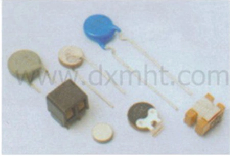
2.Type:1-disc,2-encased,3-pin form-coating;4-pin form non-coating;
3.R25 resistance:55R-55;
4.Resistance tolerance:M+/-20%;
5.Non trip current(25 ℃):070-70mA;
6.Wire shape:S-straight, A-axis formed, U-in-formed;
7.Max. Voltage:250-250V.
You can find detailed Specifications and Part No. of PTC Thermistors MZ23 Series at the bottom of this page.
The PTC Electric MZ21 is an essential component in telecom circuit protection, providing automatic, reliable, and efficient safeguarding of telecom equipment against overcurrent conditions. With its robust design and compliance with international standards, the PTC Resistor ensures the long-term stability and safety of critical telecom infrastructure. Incorporating these PTC Thermistors into your telecom systems enhances their resilience and operational efficiency, making them an indispensable choice for modern telecom applications.
Related Products
Send Inquiry
18927361658
AddB2006, Building 40, Shui'an Xindu, Xinsheng Community, Longgang Street, Longgang District, Shenzhen
E-mailinfo@dxmht.com
Copyright @ 2026 Thermistor,sensor,varistor leading manufacturer-DXMNo:84463
Copyright @ 2026 Thermistor,sensor,varistor leading manufacturer-DXM
Copyright @ 2026 Thermistor,sensor,varistor leading manufacturer-DXM


